Radiant Floor Heating Loop Calculator

Introduction: planning radiant floor loops
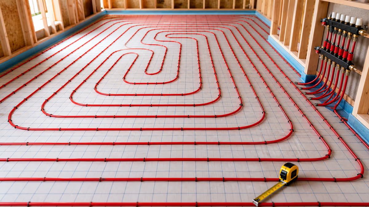
Hydronic radiant floor heating works by circulating warm water through PEX tubing arranged in repeated “loops” (circuits) under the floor surface. A manifold supplies and returns water to each loop. The practical layout questions most people start with are: (1) how much tubing to buy, (2) how many loops you’ll need, and (3) whether each loop stays under a reasonable maximum length so pressure drop and balancing stay manageable.
This calculator estimates:
- Total tubing length in the heated area based on floor area and tube spacing.
- Number of loops needed based on a max loop length you choose.
- Approximate tubing per loop assuming loops are split evenly.
- Leader (home-run) footage and a purchase length that already includes your waste factor.
It does not replace a full heat-loss and hydraulic design. Use it for early planning, ordering, and sanity-checking a proposed layout. Once you have the numbers, the Loop Layout Lab further down the page lets you draw the serpentine by hand and watch the same arithmetic play out cell by cell.
How to use the radiant loop calculator (inputs)
- Heated Area (sq ft): Net area you plan to heat (exclude tubs, cabinets, islands, stair landings, etc.).
- Tube Spacing (inches): Center-to-center spacing between adjacent tube runs. Typical ranges are 6–12 in (smaller spacing = more tube, more even heat, higher material cost, higher head loss).
- Tube Size Preset: Optional shortcut that drops a common maximum circuit length into the next field for 3/8, 1/2, 5/8, or 3/4 inch PEX. Choose “Custom” whenever your tube manufacturer publishes a different figure.
- Max Loop Length (ft): Your target maximum circuit length, measured from the manifold supply port back to the manifold return port. Common rules of thumb are about 250–300 ft for 1/2" PEX, shorter for smaller tube, longer for larger tube (details below).
- Leader/Home-Run Allowance per Loop (ft): The out-and-back tubing between the manifold and the first heated cell of that circuit. This is part of the circuit, so it is subtracted from the maximum before the field is divided.
- Waste Factor (%): Extra tubing for routing errors, bend radius, offcuts, and manifold slack. Ten percent is a common planning figure; the calculator accepts 0 to 50.
Calculation method and formulas for tubing and loops
In a simple back-and-forth (serpentine) or spiral approximation, the tubing length per square foot is inversely proportional to spacing. Converting spacing from inches to feet is the key step.
Spacing in feet:
sft = sin / 12
Plain-text formulas: fieldTubingFt = floorAreaSqFt * 12 / spacingInches; loopCount = ceil(fieldTubingFt / maxFieldLengthPerLoopFt); leaderTubingFt = loopCount * leaderAllowanceFt; totalBeforeWasteFt = fieldTubingFt + leaderTubingFt; purchaseLengthFt = totalBeforeWasteFt * (1 + wastePct / 100).
Estimated tubing length in the heated area:
L ≈ A / sft = A ÷ (sin/12) = 12A / sin
Where:
A= heated area (ft²)s= tube spacing (in)L= estimated tube length in the heated area (ft)
MathML version of the same relationship:
Why the relationship is exact for an idealised serpentine: picture the floor divided into strips one spacing wide. Each strip of length ℓ holds exactly one tube run of length ℓ and has area ℓ × sft. Add the strips up and the tube length is always the area divided by the spacing. That is the identity the Loop Layout Lab draws one cell at a time.
Number of loops (rounded up to keep each circuit including leaders under the max):
maxFieldLengthPerLoopFt = maxCircuitLengthIncludingLeadersFt - leaderAllowanceFt
N = ceil(fieldTubingFt / maxFieldLengthPerLoopFt)
The same loop-count rule in MathML:
Approximate tubing per loop:
Lloop ≈ L / N
Important note about “extra” tubing not included
The formulas above estimate tubing in the heated field. Real installations often need additional length for:
- Home runs / leaders from the manifold to the start of the heated area and back.
- Routing around obstacles and maintaining bend radius.
- Service slack at the manifold.
As a planning allowance, many installers add something like 10–30 ft per loop (sometimes more) depending on manifold location and routing complexity. If your manifold is far from the room, measure or budget accordingly so you don’t under-order tubing.
Typical max loop lengths (rule of thumb)
Maximum loop length is mainly about keeping pressure drop manageable so the circulator can deliver the needed flow and loops can be balanced. Exact limits depend on tube diameter, flow rate, fittings, layout, and acceptable head loss.
| PEX size | Common max loop length (ft) | Where it’s often used | Notes |
|---|---|---|---|
| 3/8 in | 150–200 | Small bathrooms, tight retrofits | Higher head loss; keep loops short |
| 1/2 in | 250–300 | Most residential rooms | Common balance of cost and hydraulics |
| 5/8 in | 300–400 | Larger zones, open areas | Lower head loss; larger bend radius |
| 3/4 in | 400–600 | Commercial / special cases | Often overkill for typical homes |
Interpreting the tubing, loop, and purchase numbers
- Total tubing length helps with ordering PEX and planning routing. Remember to add the leader/home-run allowance.
- Number of loops informs manifold port count and how you might divide zones (e.g., one room may be multiple loops on the same thermostat/zone valve).
- Length per loop is a rough target. In practice you’ll try to keep loop lengths similar so balancing is easier. If one loop is much longer than others, it may receive less flow and deliver less heat.
- Floor area per loop is often the easier number to work with on site: multiply the field length per loop by the spacing in feet and you get the area that circuit can serve, which tells you where to chalk the dividing line between circuits.
Worked example: 450 ft² kitchen at 9-inch spacing
Scenario: You have a 450 ft² kitchen/dining area. You want 9-inch spacing, 1/2" PEX circuits capped at 300 ft including leaders, about 30 ft of leader per loop, and a 10% waste factor. These are the calculator's default inputs, so pressing Compute Layout reproduces every number below.
- Convert spacing: 9 in = 9/12 = 0.75 ft
- Total tubing in the heated field:
L ≈ A / sft = 450 / 0.75 = 600 ft - Field length available per loop:
300 − 30 = 270 ft - Loops needed:
N = ceil(600 / 270) = 3 - Tubing per loop:
Lloop ≈ 600 / 3 = 200 ftof field tubing, about 230 ft per circuit with its leader - Floor area per loop:
200 × 0.75 = 150 ft², so the room divides into three roughly equal 150 ft² strips - Leader tubing: 3 × 30 = 90 ft, giving 690 ft before waste
- Purchase length: 690 × 1.10 = 759 ft
Why leaders matter: if you ignored leaders and capped loops at 300 ft of field tubing, ceil(600 / 300) = 2 loops would look sufficient — but each circuit would then run about 330 ft including its leader and overshoot the hydraulic cap. That is why the calculator subtracts the leader allowance from the maximum circuit length before dividing up the field.
Spacing trade-offs (quick comparison)
Smaller spacing increases tube length per area and typically improves floor surface temperature uniformity and heat output capability (assuming the rest of the system supports it). Here’s how spacing alone changes estimated tubing for a fixed area:
| Heated area (ft²) | Spacing (in) | Estimated tube length in area (ft) | What it tends to mean |
|---|---|---|---|
| 600 | 12 | 600 | Common for slabs / moderate heat density |
| 600 | 9 | 800 | More tube, more even surface temps |
| 600 | 6 | 1200 | High tube density; higher head/material cost |
Limitations and assumptions (read before building)
- Heat loss not included: The calculator does not determine whether your spacing/water temperature can meet the room’s heat load. Building insulation, glazing, air leakage, and climate drive required output.
- Floor assembly matters: Slab-on-grade vs. thin-slab vs. staple-up under subfloor will change output and required water temperatures. So do transfer plates and insulation below/around the tubing.
- Floor covering R-value: Tile, vinyl, engineered wood, carpet/pad all change how much heat reaches the room and how evenly it spreads.
- Leaders are an allowance, not a measurement: Manifold-to-room supply/return runs vary with manifold placement. Measure the real route once the manifold location is fixed.
- Hydraulics simplified: Max loop length is treated as a hard cap, but real head loss depends on tube size, flow rate (GPM), water temperature/viscosity, and fittings. Consult manufacturer pressure-drop charts for final design.
- Layout geometry ignored: Real rooms have odd shapes, obstacles, and edge zones that change exact footage. The calculator assumes the whole net area can be covered at one uniform spacing.
- Even loop split assumed: Dividing the field evenly by the loop count is the ideal case. Room geometry usually forces a few percent of imbalance, which the manifold balancing valves absorb.
- Not code/engineering advice: Verify local code requirements, oxygen-barrier needs, mixing/controls, slab insulation, and boiler/heat-pump design with a qualified professional.
Practical tips
- Keep loops similar in length within a zone to simplify balancing.
- Plan manifold placement to minimize leader lengths (saves tubing and reduces head loss).
- Don’t push max loop length “just because it fits”; shorter loops often perform and balance better.
- Tighten spacing at the perimeter rather than everywhere: a 6-inch edge band along exterior walls with 12-inch spacing in the middle often beats a uniform 9 inches for the same tubing budget.
- Order a little extra to cover routing, mistakes, and future repairs (common practice is a small percentage plus leader allowance).
Radiant loop planning: frequently asked questions
How much PEX tubing do I need for radiant floor heating?
A quick estimate is 12 times the net heated area in square feet divided by the tube spacing in inches. For example, 450 sq ft at 9-inch spacing needs about 600 ft of tubing in the heated field, plus leader runs to the manifold and a waste allowance.
What is the maximum loop length for 1/2 inch PEX?
A common rule of thumb is about 250 to 300 ft per circuit for 1/2 inch PEX, including leaders, to keep pressure drop manageable. Smaller tube needs shorter loops (150-200 ft for 3/8 inch) and larger tube can run longer (300-400 ft for 5/8 inch). Verify against the manufacturer's pressure-drop charts.
Why should radiant loops be similar lengths?
Water follows the path of least resistance, so a loop that is much longer than its neighbors receives less flow and delivers less heat. Keeping circuit lengths similar at the manifold makes balancing much easier.
What tube spacing should I use for radiant floor heating?
Most residential designs use 6 to 12 inch center-to-center spacing. Nine inches is a common default for living spaces, tighter 6 inch spacing suits bathrooms, high-loss rooms, and edge zones near exterior walls, and 12 inches can be enough for slabs with modest loads. Tighter spacing costs more tubing and adds head loss but delivers more even floor temperatures.
How do I split a room into loops of similar length?
Divide the field tubing by the loop count the calculator returns, then plan each circuit to cover roughly the same floor area. At 9-inch spacing one loop carrying 200 ft of field tubing serves about 150 sq ft, so a 450 sq ft room splits neatly into three 150 sq ft strips. Equal strips keep the circuits within a few percent of each other, which is close enough for the manifold balancing valves to trim out.
Sources and further reading for radiant loop design
The tubing-per-area relationship (12A ÷ spacing) and the rule-of-thumb circuit caps by tube size follow manufacturer hydronic design manuals and published panel-heating design guidance. Final loop lengths must be verified against your tube manufacturer's pressure-drop charts, because head loss depends on flow rate, water temperature, and fittings as well as length.
- U.S. Department of Energy, Energy Saver — Radiant Heating: plain-language overview of hydronic radiant floor systems and where they perform well.
- Building America Solution Center (PNNL/DOE) — Hydronic Radiant Floor Heating: installation guidance on tube spacing, slab insulation, and manifold detailing.
- ASHRAE Handbook — HVAC Systems and Equipment, “Panel Heating and Cooling” chapter: the engineering treatment of panel output, surface temperature limits, and tube spacing effects.
- Uponor — Complete Design Assistance Manual and PEX pressure-drop data: manufacturer circuit-length and head-loss tables of the kind this calculator's maximum-loop-length input stands in for.
- PEX Universe — radiant loop length guidance by tube size: a convenient summary of the 3/8, 1/2, and 5/8 inch circuit-length rules of thumb used in the table above.
Use positive values for the heated area, spacing, and maximum loop length. Leader allowance and waste factor can be zero.
Status messages will appear here.
Loop Layout Lab: draw the tubing this calculator just sized
This is the calculator's own arithmetic played on a floor. Every level hands you a room, a tube diameter, and a target on-centre spacing, and the grid is scaled so one cell is exactly one spacing square. Steer the laying head and each cell you cross adds one spacing-width of PEX — the same L = 12A / s identity the calculator uses. Cold blue floor warms toward orange as tube gets near it, the readout tracks the on-centre spacing you are actually achieving, and each circuit is cut off when it hits the maximum loop length for that tube size. Finish the room inside the loop count the calculator says you need.
Tube 3/8 in PEX
Target spacing 6.0 in
This loop 0.0 ft
Allowance left 160.0 ft
Loops 0 / 1
Field tubing 0.0 ft
Coverage 0% / 95%
Spacing achieved —
Score 0
Best 0
Press Start layout run, then use the arrow keys or drag on the floor to lay tubing from the manifold.
Keyboard (focus the floor plan first): ← → ↑ ↓ move the laying head one spacing square, hold Shift with an arrow to run the head to the far wall, Space starts a loop, pauses it, or resumes it when the head is parked back on the loop end, Backspace pulls one cell of tubing back, R restarts the level, N loads the next room. Pointer and touch: press on a cell to start laying there and drag to trail the tube behind the head.
- Cold floor — no tubing within one spacing square
- Warming — tubing is one square away
- Heated — tubing runs through this square
- Loop 1 tubing, fed from the manifold at the left wall
- Loop 2 tubing — started once loop 1 hits its length cap
- Island or cabinet run — no tubing, no credit for area