
Introduction to leach field sizing and soil absorption
Leach field sizing is controlled by local septic code, a qualified soil evaluation, site conditions, and permitting; every number here is a planning estimate rather than a construction design.
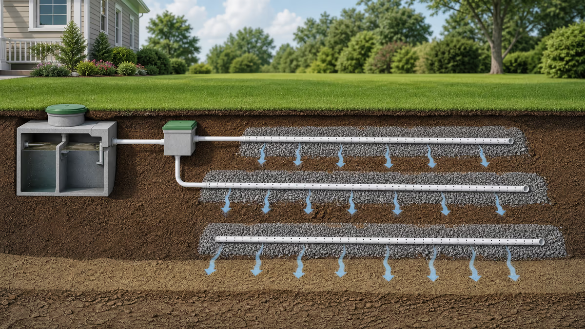
A leach field, also called a drain field or soil treatment area, receives clarified wastewater after it leaves a septic tank. Effluent moves through the trench bottom, a biological layer called the biomat, and unsaturated native soil. Those layers slow and treat the water before it can reach groundwater. A field that is too small may pond or back up; a field that is needlessly large can consume the only suitable replacement area on a lot. This calculator keeps the arithmetic transparent so you can see why soil and design flow matter more than a simple bedroom rule of thumb.
The calculator uses design flow, a soil loading rate, trench width, and a maximum lateral length. It then applies any locally approved gravelless-chamber credit and an optional safety margin. The result is not a guarantee that a field fits: wells, watercourses, bedrock, seasonal groundwater, slopes, easements, trees, and driveway space can all rule out an otherwise adequate rectangle. Calculations run in your browser and are not sent to this site.
How to use this leach field size calculator
Start the leach field estimate by choosing a preset or entering the basis your local code uses. Residential permits commonly use bedrooms, because future occupancy can change, while a cabin or a nonresidential project may use occupants or a known daily flow. Next, enter either a percolation time or the application rate supplied by a soil evaluator. The calculator converts accepted percolation values with the displayed reference table.
- Set the flow basis and daily-use assumption required for the property.
- Enter the percolation result or a local loading rate in gpd/ft².
- Describe creditable trench width, lateral-run limit, and trench spacing.
- Add only an approved chamber credit, a planning margin, reserve area, and an optional material price.
- Calculate, read the warnings, and use the output as a conversation starter with the health department or designer.
Design flow for bedrooms, occupants, and gallons per day
Leach field design flow is a code value, not a forecast of the people currently in a house. A common planning assumption is 120 gallons per day for each bedroom, although published state values often range from 110 to 150. The familiar bedroom calculation is gallons per day, where is the bedroom count. A three-bedroom example therefore begins at 360 gpd. Occupant and direct-flow modes are useful for preliminary comparisons, but they can be smaller than the permitted residential flow.
Garbage grinders usually affect solids handling rather than hydraulic loading. Many jurisdictions require more tank capacity, an effluent filter, or both instead of automatically enlarging the field. The calculator therefore reports the representative tank consequence separately when bedroom sizing is selected.
Percolation rate, soil loading, and leach field acceptance
A perc test records the minutes required for water to fall one inch in a prepared and pre-soaked hole. A soil evaluation may instead establish texture, structure, depth, and a long-term acceptance rate directly. Either route produces a soil application rate in gallons per day per square foot of trench bottom. Smaller rates mean less creditable absorption and a larger field. Very rapid soil may not provide enough treatment, while very slow soil commonly cannot support a conventional gravity trench.
| Percolation rate (min/in) | Application rate (gpd/ft²) |
|---|---|
| Faster than 1 | Too fast for a standard gravity trench |
| 1–5 | 1.20 |
| 6–7 | 1.00 |
| 8–10 | 0.90 |
| 11–15 | 0.80 |
| 16–20 | 0.70 |
| 21–30 | 0.60 |
| 31–45 | 0.50 |
| 46–60 | 0.45 |
| Slower than 60 | Alternative engineered system usually required |
The local health department’s adopted table governs. Some places use soil texture and structure rather than perc time, and older tables may contain rates that a current conventional-trench rule no longer accepts. The conservative long-term rate accounts for the biomat that develops below an operating trench.
Formula walkthrough for leach field area and trench layout
Plain-text formulas: absorptionArea = dailyDesignFlow / soilLoadingRate; totalTrenchLength = adjustedDesignArea / trenchWidth; reserveFootprint = 2 * primaryFootprint when a full reserve is required.
The required absorption area is daily design flow divided by the allowed soil application rate:
Here is gallons per day and is gpd/ft². For a conventional trench, this is credited trench-bottom area, not the whole disturbed yard. The calculator reduces area by an entered approved product credit, adds the safety margin, and converts the resulting area to total trench length using trench width :
The adjusted design area includes both the product credit and planning margin. In the following expression, is the approved credit percentage and is the selected safety margin percentage:
Long trenches do not distribute gravity flow evenly, so the total is divided into laterals. The calculator uses equal runs. It estimates the field strip from the number of laterals, their width, and undisturbed spacing. Its schematic footprint calculation can be expressed as:
In that footprint equation, means undisturbed space between trench edges. If a full reserve is required, the calculator sets aside twice this illustrative primary footprint:
With a price input, planning material cost is , where is price per square foot of absorption area. These equations describe the calculator’s planning arithmetic; permit drawings must still account for actual contours, setbacks, access, and any distribution method required by the authority having jurisdiction.
Leach field trenches, beds, chambers, and area credits
Conventional trench rules explain why a wider excavation is not always a shortcut. Many codes credit only 24 to 36 inches of trench bottom; a wider excavation can be treated as an absorption bed, with a different and often lower loading rate. Similarly, a large field is usually several parallel laterals from a distribution box rather than one exceptionally long run. Open-bottom chamber products may receive a 25% to 40% reduction in some jurisdictions, but other counties allow no credit. Leave the credit at zero until the product and percentage are specifically approved for the site.
Worked example: three-bedroom leach field in loam soil
For a three-bedroom home at 120 gpd per bedroom, gpd. A 25 min/in perc result maps to 0.60 gpd/ft² in the reference table. The basic area is ft². A 10% safety margin makes the design area 660 ft². With 2-foot trenches, the field needs 330 linear feet. A 100-foot maximum run produces four laterals of 82.5 feet each.
With 6 feet of undisturbed soil between four 2-foot laterals, the illustrative primary strip is about 26 feet wide by 82.5 feet long, or roughly 2,150 ft² of yard. A 100% reserve would set aside roughly 4,300 ft² before setbacks and irregular lot geometry. At an illustrative $6 per ft², the 660 ft² absorption area gives a material estimate of $3,960. Installed septic costs can be much higher because excavation, rock or chambers, piping, distribution, permits, testing, and restoration are separate costs.
Leach field site constraints, setbacks, and replacement area
A leach field square-foot answer is only one part of site suitability. Conventional systems commonly need 2 to 4 feet of unsaturated native soil below the trench bottom and above seasonal high groundwater, bedrock, or another restrictive layer. Typical horizontal setbacks can include about 100 feet to a well, 50 to 100 feet to surface water, and 10 to 20 feet to buildings, property lines, and water lines, but local rules vary. Soil pits, mapped setbacks, slope, utilities, trees, and access must all be reviewed before a field footprint is treated as buildable.
Septic tank sizing and leach field maintenance
The septic tank protects the leach field by retaining solids; it is sized separately but the two components fail together. A representative residential table uses 1,000 gallons for one to three bedrooms, 1,250 for four, 1,500 for five, and 1,750 for six, with 250 more gallons per additional bedroom. A grinder may add 250 gallons under the cited New York standard. Pumping on an appropriate schedule, protecting laterals from vehicles, directing roof drainage away from the field, and keeping deep-rooted plants away help preserve the infiltrative surface.
| Bedrooms | Minimum capacity | With garbage grinder |
|---|---|---|
| 1–3 | 1,000 gal | 1,250 gal |
| 4 | 1,250 gal | 1,500 gal |
| 5 | 1,500 gal | 1,750 gal |
| 6 | 1,750 gal | 2,000 gal |
| Each additional bedroom | +250 gal | +250 gal |
Limitations of this conventional leach field estimate
This leach field calculator models a conventional gravity-trench planning case. It does not design mounds, sand filters, aerobic treatment, pressure distribution, drip dispersal, curtain drains, or engineered fill. It also cannot verify a perc-test procedure, vertical separation, trench depth, aggregate requirements, groundwater, setbacks, or a reserve area. Use conservative local inputs and let the permitting authority and qualified onsite wastewater professional decide the final system.
Sources for the leach field sizing reference values
Source metadata: the loading-rate and tank-capacity values are illustrative planning references checked against New York State Appendix 75-A and federal onsite-wastewater guidance; the current local code and permitting authority control.
These leach field reference values are intended to make assumptions visible, not to replace local law. The calculator’s conversion table and representative tank capacities were checked against New York State Appendix 75-A and compared with federal onsite wastewater guidance. Where those sources or your county differ, the county’s adopted rule controls.
- U.S. Environmental Protection Agency, Onsite Wastewater Treatment Systems Manual (PDF), EPA/625/R-00/008.
- New York State Department of Health, Appendix 75-A, Wastewater Treatment Standards (PDF).
- New York State Department of Health, Residential Onsite Wastewater Treatment Systems Design Handbook.
Leach field sizing frequently asked questions
How big should a leach field be for a three-bedroom house?
A 360 gpd planning flow in 0.60 gpd/ft² soil requires 600 ft² of trench-bottom area before a margin. With 2-foot trenches that is 300 linear feet, and a margin or reserve area increases the land needed.
Can this calculator replace a septic designer or permit approval?
No. The tool explains preliminary sizing only. A permit depends on local code, test methods, soil depth, setbacks, reserve land, and the health department’s review.
What soil loading rate should I enter?
Use the rate issued by your soil evaluator or local code. If you only have a valid perc time, select percolation mode; the calculator applies its reference conversion table and warns outside its conventional range.
What does a perc result slower than 60 minutes per inch mean?
Most modern conventional gravity-trench rules do not credit soil that slow. A mound, sand filter, aerobic unit, drip dispersal, another engineered approach, or no onsite system may be the outcome.
Do chambers make a smaller leach field acceptable?
Only if the jurisdiction grants a credit for the exact approved chamber product. Credits often range from 25% to 40%, but they can be zero, so do not assume a manufacturer claim is a permit allowance.
Why does trench width stop helping?
Code commonly caps credited trench-bottom width. A wider excavation may be an absorption bed, which is governed by different loading and layout rules rather than simply reducing required yard area.
Conclusion: using a leach field estimate for responsible planning
This leach field calculator connects daily wastewater flow to soil capacity, trench length, lateral layout, and reserve land. Try reasonable local scenarios to understand the site’s constraints, then bring the result and the underlying soil information to a licensed designer and the local health department before excavation.
Drainfield Designer: lay a field that actually absorbs
This optional yard game turns the leach field calculation into a visual challenge. Lay 10-foot trench segments that provide enough soil capacity for the site’s daily flow while avoiding the house, well setback, and property edges. The score rewards a clean layout that absorbs the flow without using unnecessary trench-bottom area.
Design flow 360 gpd
Field capacity 0 gpd
Trench bottom 0 ft²
Segments laid 0
Area efficiency —
Setback breaches 0
Score 0
Best 0
Pick a site, lay trench segments on soil that can absorb the flow, then run the flow test.
Keyboard: ← → ↑ ↓ move, Space or Enter lay or remove, T tests flow, and Backspace clears. Pointer and touch: tap cells to lay or remove segments.
- Sandy loam — 0.90 gpd/ft²
- Loam — 0.60 gpd/ft²
- Silt loam — 0.45 gpd/ft²
- Clay — no conventional credit
- Absorption trench segment
- Setback zone